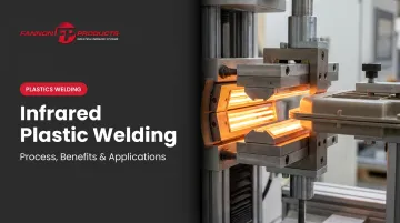
Infrared plastic welding is a non-contact thermal technique that uses radiant IR energy to melt thermoplastic joint surfaces without the heat source ever touching the part. The result is a clean, strong, repeatable weld — achieved without adhesives, solvents, or the contamination risks that contact-based methods introduce.
This article is written for engineers, production managers, and procurement teams in automotive, medical, and industrial manufacturing. It covers how the process works step by step, what advantages it offers over other welding methods, which applications it's best suited for, and — just as importantly — where it falls short.
Key Takeaways
- IR welding uses radiant energy from IR lamps to melt thermoplastic joint surfaces, then presses them together to form a unified weld bond
- Non-contact heating eliminates tooling contamination, prevents material sticking, and reduces flash compared to hot plate welding
- Widely used in automotive and medical device manufacturing where clean, contamination-free joints are non-negotiable
- Cycle times typically run 20–60 seconds — longer than hot plate welding's 8–30 seconds — so takt time constraints matter
- Not suitable for thermosets, highly transparent materials without absorptive additives, or applications where IR tooling's higher upfront cost can't be justified
What Is Infrared Plastic Welding?
Infrared plastic welding is a non-contact thermal joining process. IR lamps emit electromagnetic radiation — short-wave emitters peak at roughly 1.0–1.2 µm, medium-wave emitters at 2.0–2.5 µm — that is absorbed by the thermoplastic surface and converted to heat. That heat melts a thin layer at the joint interface. The IR source is then withdrawn, and the two molten surfaces are pressed together and cool into a continuous weld bond.
The result: two separate plastic parts joined into one, with a bond that approaches the strength of the base material — no adhesives, no solvents, and no physical contact with the heat source.
How It Compares to Similar Processes
| Method | Heat Transfer | Contact with Plastic | Flash Level | Tooling Cost |
|---|---|---|---|---|
| Hot plate welding | Conductive | Direct contact | Higher | Lower |
| IR welding | Radiant | No contact | Lower | ~30–40% more than hot plate |
| Laser welding | Focused radiant | No contact | Minimal | Higher |
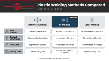
According to Assembly Magazine, IR tooling typically costs 30–40% more than equivalent hot plate tooling — a real consideration for lower-volume production. TWI classifies IR welding as a non-contact variation of hot plate welding: more precision and cleanliness than hot plate, less optical complexity than laser.
How the Infrared Plastic Welding Process Works
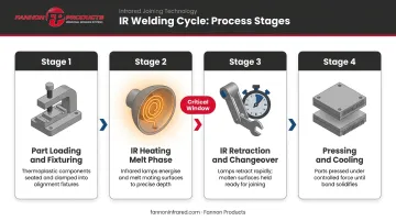
The core sequence is straightforward: heat the joint surfaces with IR radiation, withdraw the source, press the molten surfaces together, hold under pressure until cool. Each phase has specific requirements that determine weld quality.
Step 1: Part Loading and Fixturing
Parts are loaded into precision holding fixtures that maintain alignment throughout the cycle. The IR emitter array positions between the two part halves at a controlled standoff distance, ensuring heat transfer occurs through radiation only. Fixture design is not an afterthought: any misalignment at this stage propagates through the entire weld.
Step 2: Heating (Melt Phase)
IR energy activates and targets the joint area of each part half. The plastic surface absorbs the radiant energy, heats, and transitions to a molten state.
One key distinction from hot plate welding: no material displacement occurs during the IR melt phase. The molten material stays in place at the joint rather than being physically reshaped by contact with a heated platen. Forward Technology reports typical total displacement of just 0.030 inches, which reduces flash. The tradeoff: part dimensional accuracy from molding is critical. IR welding won't self-correct warped or out-of-tolerance weld ribs the way conductive contact can.
The transition window (the time between IR retraction and part contact) is critical. ScienceDirect describes this changeover phase as elapsed time from heat-source removal to part contact, and states it should be as short as possible. Surface cooling during changeover forms a skin layer that resists bonding and weakens the joint.
In a 2024 study on glass-filled PA6, researchers used approximately 1.7 seconds of changeover. Even that brief window required careful management.
Force-controlled joining systems continuously monitor and adjust pressure to prevent squeezing out too much molten material, which would create a cold, under-filled weld.
Key Benefits of Infrared Plastic Welding
No Tooling Contamination
The IR emitter never touches the plastic. That eliminates two persistent problems in hot plate welding: material building up on the heated platen over time, and foreign contamination introduced into the weld zone.
In medical and food-contact applications, a particulate-free joint is a hard requirement — not a design preference. Both Dukane and Emerson cite this as a primary reason IR welding is favored for medical products.
Controlled Melt Zone Reduces Flash
Because radiation heats only the targeted joint surface, the melt zone is narrow and controlled. Less material flows outside the weld area, which means:
- Less internal flash that can restrict flow in fluid-carrying assemblies
- Reduced or eliminated need for flash traps in part design
- Cleaner aesthetics on visible joint lines
- Lower risk of particulate contamination from flash breakoff
Plastics Decorating reports that reduced displacement in IR welding can often eliminate flash traps and cosmetic flash-hiding design features entirely.
Hermetic Sealing Capability
With correct parameters, IR welding produces strong, hermetic joints — air-tight and pressure-capable. Plastics Decorating's industry review cites 100% gas-tightness as a documented advantage, and Forward Technology confirms hermetic weld capability. That makes IR welding a reliable choice for pressure-holding, fluid-containing, and gas-tight assemblies.
Automation and Repeatability
Every weld cycle runs on fully programmable parameters:
- IR intensity and emitter distance
- Melt time and transition time
- Joining force and weld depth
- Cooling hold time
Every cycle executes identically. Weld data can be logged for QA/QC traceability — a requirement in both automotive production and medical device manufacturing, where process records are part of regulatory compliance.
Material and Geometry Versatility
IR welding handles a broad range of thermoplastics effectively, including PP, PE, PC, ABS, PVC, HDPE, PA, and POM. Multi-emitter arrays and mask configurations can address large or contoured part geometries that would challenge a single-element system.
Industrial Applications of Infrared Plastic Welding
Automotive
Automotive is the strongest and most documented application category for IR welding. DVS Guideline 2228 cites intake pipes, ventilation parts, instrument panels, and containers for brake fluid and washer fluid as established examples. Sonimat's automotive references add dashboards, headlights, intake manifolds, and SCR system components.
The common thread runs through all of them: these parts carry fluids, route air, or sit in visible locations — conditions where internal flash, particulate contamination, or weak joints are unacceptable.
Medical and Healthcare
Emerson identifies IR welding as ideal for medical products because it produces particle-free joints. TWI includes IR welding among recommended joining techniques for polymeric medical devices. No-contact heating, minimal flash, and clean weld zones align with cleanroom requirements and sterility standards that contact welding methods struggle to meet.
Infrastructure and Industrial
PE100+ documents IR non-contact welding (IR-O) for polyethylene piping systems — a process introduced in the early 1990s that produces strong joints with minimal deformation, suited to gas and water distribution pipes.
Custom IR systems for industrial plastics manufacturing can be configured for specific welding fixture geometries, heated lengths, and power requirements. Fannon Products' infrared systems for the plastics industry cover:
- Welding and forming
- Softening and curing
- Drying applications
Each system is built around their 96% radiant efficiency lamps with instant thermal response. For application-specific configurations, contact their engineering team at sales@fannonir.com or 810-794-2000.
Key Factors Affecting Weld Quality — and When IR Welding May Not Fit
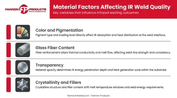
Material Properties Drive Everything
How a thermoplastic absorbs IR energy at the emitter's wavelength determines how quickly and deeply the joint heats. Several variables shift this behavior:
- Color and pigmentation: Carbon black pigments in black PA6 GF50 absorb surface radiation rapidly, causing shallow heating penetration rather than even melt-layer development (Springer, 2024)
- Glass fiber content: Glass fibers act as scattering centers, inhibiting IR depth penetration in highly filled materials — PA6 with 50% glass fiber still welds, but requires careful parameter validation
- Transparency: Clear or highly transparent materials may transmit IR rather than absorb it; an absorptive additive or modified process design is needed
- Crystallinity and fillers: Both shift how much IR energy a material absorbs versus reflects at a given wavelength, which directly affects melt uniformity
For any new material or part geometry, upfront testing and parameter development are essential — no shortcut replaces measured data.
Part Dimensional Consistency Is Non-Negotiable
IR welding provides no corrective contact during the melt phase. Warped weld ribs, out-of-tolerance dimensions, or inconsistent wall thicknesses each create uneven melt depth, resulting in incomplete fusion across the joint area.
Established design guidelines for IR welding specify minimum weld rib widths, material overlap zones, and required clearance from nearby features. Treating these as baseline requirements — not suggestions — is what separates consistent joints from field failures.
When to Choose a Different Method
IR welding is the wrong choice in these situations:
- Thermoset plastics (epoxies, phenolics) — they don't re-melt, so thermal welding of any kind won't work
- Highly transparent materials without absorptive additives or a through-transmission setup
- Applications where cycle time is the primary constraint — hot plate welding runs 8–30 seconds versus IR's 20–60 seconds
- Budget-sensitive, lower-volume runs where IR tooling's 30–40% cost premium over hot plate isn't justified
- Assemblies with internal temperature-sensitive components (batteries, PCBs, O-rings) that prolonged IR exposure could damage
Frequently Asked Questions
Which plastics cannot be welded with infrared plastic welding?
Thermoset plastics (epoxies, phenolics) cannot be IR welded because they cure chemically and won't re-melt. Highly transparent amorphous thermoplastics transmit rather than absorb IR radiation, requiring an absorptive additive or interface layer to weld successfully. Heavily filled or reflective materials may also need parameter adjustments or alternative techniques.
Can infrared plastic welding melt plastic?
Yes — IR welding melts a thin layer at the joint surface in a controlled, deliberate way. Controlling IR intensity and exposure time ensures only the weld interface reaches molten temperature, leaving the rest of the part dimensionally stable and undamaged.
What is the best plastic welding method?
It depends on material type, part geometry, joint strength requirements, cycle time, and cleanliness needs. IR welding is preferred for non-contact heating, minimal flash, or high-temperature thermoplastics. Hot plate welding suits high-volume applications where faster cycles and lower tooling costs outweigh contamination concerns.
How does infrared welding differ from hot plate welding?
Hot plate welding presses a heated platen directly against the plastic rib, physically displacing and reshaping the surface — which can self-correct some molding inconsistencies. IR welding heats at a standoff distance with no physical contact, eliminating sticking and contamination but requiring tighter dimensional control of the molded parts.
What is the typical cycle time for infrared plastic welding?
Assembly Magazine reports typical IR welding cycle times of 20–60 seconds, compared to 8–30 seconds for hot plate welding. The difference comes from radiation absorption and heat conduction rates. Material type, IR intensity, part geometry, and target melt depth all affect where a specific application falls within that range.