UV LED curing systems solve this by separating heat from cure. The result is a process that runs cooler, faster, and in a fraction of the floor space.
This article walks through the design basics: how the two-stage process works, what components a UV LED powder coating line requires, the critical parameters engineers must specify, and where the technology fits — and where it doesn't.
Key Takeaways
- UV LED powder coating combines a brief low-temperature melt phase with near-instant UV photopolymerization, cutting total line time to roughly 2–5 minutes vs. 30+ for thermal cure
- The melt zone (IR or convection heat, typically 100–130°C) and UV LED curing station are distinct equipment zones
- Wavelength matching between the UV LED and the powder's photoinitiators determines cure completeness — a mismatch causes incomplete cure regardless of lamp power
- UV LED curing is line-of-sight; shadowed surfaces won't cure without multi-angle lamp arrangements or rotating hangers
- MDF, thermoplastics, and heat-sensitive assemblies become viable substrates — materials conventional thermal curing rules out entirely
The Two-Stage UV LED Powder Coating Process
UV LED powder coating looks similar to conventional powder coating from the outside : electrostatically applied powder, conveyor line, done. The chemistry, however, is fundamentally different.
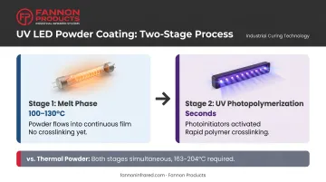
Conventional thermal powder coating does two things simultaneously: heat melts the powder particles and drives the crosslinking reaction. You can't separate them, which is why substrates must reach and hold 163–204°C for an extended period. UV LED powder coating decouples these into two distinct, independently controlled stages.
Stage 1: The Melt Phase
Powder applied to the substrate enters a heat zone — typically medium-wave IR emitters or convection heat — where it's brought to approximately 100–130°C. At this temperature, the powder particles flow together into a continuous, smooth film. No crosslinking occurs yet.
The substrate is only exposed to moderate heat for a short time. Keyland's technical data shows typical melt times by substrate:
- Metal: 1–4 minutes
- MDF: 1–3 minutes
- Plastics and composites: 0.5–3 minutes
Times vary based on substrate mass and formulation.
For MDF specifically, preheat surface temperature targets are typically just 60–70°C — far below the threshold that causes outgassing or substrate damage.
Stage 2: UV Photopolymerization
Immediately after the melt zone, the still-molten film enters the UV LED curing station. Here, high-intensity UV light activates photoinitiators embedded in the powder formulation — chemical compounds that absorb UV energy at specific wavelengths and trigger rapid crosslinking of the polymer chains.
According to ChemQuest's overview of UV-curable powder coatings, the UV cure itself takes "very few seconds" once the molten film is exposed.
Because heat and cure are fully independent, line engineers can optimize each stage separately — adjusting melt temperature for substrate sensitivity without touching cure intensity, or dialing in UV dose without adding dwell time in the heat zone. That flexibility is what makes the process viable for wood, plastic, and heat-sensitive composites that conventional powder coating would damage or destroy.
Key Components of a UV LED Powder Coating Line
A UV LED powder coating line contains three functional zones: the melt zone, the UV LED curing station, and the conveyance and controls system. The overall line length is significantly shorter than a thermal equivalent — Products Finishing reports a UV-cured powder plant at 2,050 sq ft versus 16,000 sq ft for a solventborne finishing plant running equivalent line speed (note: this comparison is against solventborne, not thermal powder specifically — equivalent-throughput thermal powder line data isn't widely published).
The Melt Zone: IR Heating
The melt zone brings the part to the powder's flow temperature using medium-wave IR emitters, gas convection, or a combination of both. Medium-wave IR is commonly preferred for its speed and precise controllability — output can be adjusted instantly, unlike a thermal oven that takes time to stabilize.
Key melt zone design inputs:
- Lamp wattage and density relative to part mass and geometry
- Dwell time — targeting 1–2 minutes for most applications (longer for heavy metal parts)
- Lamp-to-part distance — affects surface temperature uniformity
- Staged or ramped heating — needed for dense substrates or complex profiles to avoid surface defects
Fannon Products manufactures medium-wave quartz IR lamps in virtually any length, wattage, and voltage — including configurations with 24K gold reflectors for directional energy delivery. Their twin-tube IR lamps deliver 96% radiant efficiency with instant response time, which matters here because precise temperature control directly affects film quality.
Custom fixture assemblies can be engineered around specific part geometries, whether flat MDF panels on a flat-bed conveyor or 3D metal parts on overhead hangers. Reach Fannon's engineering team at 810-794-2000 for application-specific sizing.
The UV LED Curing Station
Immediately after the melt zone, the molten film enters the UV LED curing station. Timing is critical: the film must still be molten at lamp entry, and the lamps must deliver sufficient dose for full cure in a single pass.
The biggest constraint: UV curing is line-of-sight. Every coated surface must have direct exposure to the UV light source. Common approaches for 3D parts include:
- Stationary multi-angle arrangements (top, side, and bottom lamps)
- Rotating part hangers to cycle all surfaces through the lamp field
- Robotic lamp positioning for complex geometries
Fannon Products manufactures UV LED curing systems in 3-inch, 6-inch, and 9-inch curing module configurations, all operating at 395–405 nm with a power intensity of 16 W/cm². Each module uses an LED reflector system that focuses output directly at the substrate. For powder coating applications, wavelength compatibility with the specific powder formulation should be confirmed with the powder supplier before specifying equipment.
Wavelength Matching: Why Photoinitiator Compatibility Matters
Photoinitiators absorb UV energy at specific wavelengths — if the LED emission spectrum doesn't match that absorption range, the cure reaction won't initiate regardless of energy dose. As Products Finishing explains in its LED curing overview, a mismatch here means the coating stays uncured even under high-intensity lamps.
Common wavelengths in UV powder coating: 365 nm, 385 nm, and 395 nm. DSC testing published by Keyland/Products Finishing showed a 395 nm UV LED successfully curing clear, black, white, and other non-conflicting pigmented UV powder coatings — though the correct wavelength for any specific formulation must always be verified with the powder supplier.
Conveyance, Cooling, and Controls
Conveyor stability during the melt phase is critical — vibration can disturb the flowing film before it cures. Line speed must be calculated to deliver the required melt dwell time and UV exposure dose simultaneously.
Because parts exit the process at 100–130°C rather than the 200°C+ typical of thermal lines, the cool-down zone can be much shorter, further reducing total line footprint.
Critical Design Parameters: Irradiance, Dose, and Pigmentation
Two UV output parameters drive every lamp specification decision.
Irradiance (intensity) is measured in mW/cm² — the UV power delivered per unit area at a given distance. Energy dose is measured in mJ/cm² — the total UV energy received as the part moves through the lamp field. Both must be sufficient for complete cure.
Keyland's UVMax technical data provides reference ranges for UV powder curing:
| Band | Dose Range | Irradiance Range |
|---|---|---|
| UVA | 400–1,200 mJ/cm² | 150–700 mW/cm² |
| UVB | 300–700 mJ/cm² | 100–500 mW/cm² |
| UVC | 60–150 mJ/cm² | — |
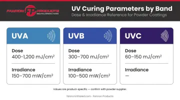
These are product-specific values — not universal targets. Always confirm cure requirements with the powder formulation supplier.
How Line Speed Affects Dose
The faster the conveyor, the less time the part spends in the UV field, reducing total energy dose. Slower speeds increase dose but reduce throughput. Use this formula to find the balance:
Dose (mJ/cm²) = Irradiance (mW/cm²) × Exposure Time (seconds)
Set conveyor speed based on the minimum dose required for full cure, then verify at full production speed with actual parts.
The Pigment Challenge
Dose calculations assume the UV energy reaches the photoinitiators — but pigmentation interferes with that path. Dark pigments, especially carbon black, absorb UV before it penetrates to cure depth. White pigments scatter it instead of transmitting it.
Both effects mean heavily pigmented formulations need higher lamp power than clear or lightly tinted coatings. Before locking in lamp specifications for any opaque or dark color, ask your powder supplier for cure window data specific to that formulation — not just general guidelines.
Substrate Suitability
UV LED powder coating expands the range of powder-coatable substrates significantly. The process works because peak substrate temperature stays in the 100–130°C range for a short time — well below the thresholds that damage wood composites, thermoplastics, and assembled components.
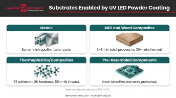
Suitable substrate categories:
- Metals (aluminum, steel) — UV LED delivers the same finish quality as conventional powder coating with faster process cycles
- MDF and wood composites — UV LED is now the established approach; PCI Magazine reports total MDF finishing process times of 3–5 minutes, versus 30+ minutes for thermal
- Thermoplastics (ABS, PVC, fiberglass composites) — Keyland's Plastics Decorating data shows ABS achieving 5B adhesion and 2H pencil hardness; fiberglass and SMC reaching 50 in-lb impact resistance
- Pre-assembled components with heat-sensitive elements (electronics, gaskets, adhesives)
Geometric Limitations
Complex 3D geometries with deep undercuts or enclosed cavities create shadowing problems. Any surface that can't directly "see" a UV lamp won't cure. Parts with significant geometric complexity should go through a pre-production lamp coverage audit before committing to tooling or line configuration.
UV LED vs. Thermal Powder Coating: Key Differences
| Attribute | Thermal Powder Coating | UV Arc/Mercury Lamp | UV LED Powder Coating |
|---|---|---|---|
| Cure mechanism | Heat-driven thermoset crosslinking | Melt phase + broad-spectrum UV lamp | Melt phase + photoinitiator-triggered photopolymerization |
| Process time | 30+ minutes at cure temperature | Melt + UV (total time not well-documented) | 2–5 minutes total (melt + UV) |
| Peak substrate temp | 163–204°C | ~120°C melt; lamp IR heat adds load | 100–130°C |
| Energy profile | High sustained heat load | Energy-inefficient lamps; IR heat from lamp | 40–60% less energy than other finishing processes (MDF applications) |
| Equipment footprint | Large cure oven required | Shorter than thermal | Compact — significant floor space reduction |
| Heat-sensitive materials | Not suitable | Limited by arc lamp IR heat | MDF, plastics, composites, assemblies — established |
| Lamp life/consistency | N/A | Output degrades over time | Stable, consistent output over lamp life |
UV LED outperforms on footprint, substrate range, and energy efficiency — particularly where heat-sensitive materials or floor space are factors. Thermal powder coating remains the practical default for high-volume metal parts where peak temperatures are not a concern and a straightforward line setup is the priority.
Environmental and Energy Benefits
UV LED curing systems offer two environmental advantages that directly affect operating costs and compliance overhead.
Lower Energy Draw
UV LED lamps only draw power when a part is in the curing zone — instant on/off, no warm-up, no idle heat load. Keyland reports UV powder MDF finishing uses 40–60% less energy than comparable finishing processes. Note this figure applies specifically to MDF applications; a direct UV LED vs. thermal powder kWh-per-part comparison across all substrates isn't well-documented in published literature.
Zero VOCs and HAPs
UV-curable powder coatings are 100% solids — no solvents, no volatile organic compounds, no hazardous air pollutants. Keyland explicitly states UV powder formulations contain no solvents, VOCs, HAPs, monomers, or additives. This eliminates emission control equipment and simplifies regulatory compliance.
Frequently Asked Questions
Do UV LED powder coating systems require special powder formulations?
Yes. UV-curable powders are specifically formulated with photoinitiators that standard thermoset powders don't contain. Off-the-shelf thermal powder coatings cannot be cured with UV LED systems — the two are chemically incompatible.
Can I retrofit an existing thermal powder coating line with UV LED curing?
Retrofits are generally feasible. The spray booth and pre-treatment stages typically stay in place. The long thermal cure oven is replaced with a compact IR melt zone and UV LED curing station — that's the primary source of floor space savings.
What wavelength UV LED is most commonly used for powder coating?
365 nm, 385 nm, and 395 nm are the most common. Testing has shown 395 nm successfully curing clear, black, white, and other non-conflicting pigmented formulations. The correct wavelength must always be confirmed against the specific powder's photoinitiator absorption range before specifying equipment.
What is the "shadowing" problem in UV LED line design?
Because UV curing is line-of-sight, any surface that can't directly see a UV lamp won't cure. Recesses, undercuts, and enclosed cavities require multi-angle lamp arrangements, rotating part hangers, or both to achieve full coverage on complex 3D parts.
Is UV powder coating as durable as thermal powder coating?
Properly cured UV powder coatings deliver comparable or superior hardness, scratch resistance, and chemical resistance to thermally cured counterparts. Keyland's technical data shows pencil hardness of H–4H, impact resistance of 15–160+ in-lb, and minimum 4B adhesion by ASTM D3359.
How long does the UV LED curing step actually take?
The UV cure itself takes seconds once the part enters the lamp field. Total line time — including the melt phase — is typically 2–5 minutes for most substrates, compared to 30 minutes or more for a conventional thermal powder coating line.